New Powertrain Transmission Assembly Complex and CEP – Phase II
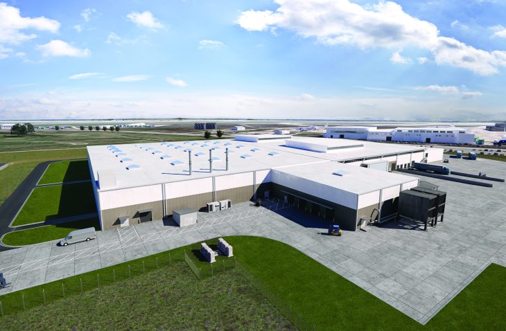
IMEG provided structural, mechanical, electrical, plumbing, and communications engineering design services for Phase II of the new Powertrain complex which encompasses the Powertrain Transmission Preassembly (PTPA) and a Central Energy Plant (CEP). The PTPA, an addition to the Dynamic Component Repair Facility (DCRF), was designed to house process equipment, including the primary tools, equipment, and processes used to repair and overhaul helicopter transmissions.
As part of the ongoing refinement of the project requirements, the design team used the DD1391 review and edit process to develop a master plan for powertrain development phases I-VIII. The phased scope of construction was adjusted to meet the $85M project cost limit per phase. Omissions in the DD1391 were addressed throughout the design development phase to accommodate the scope within budget.
Upon discovery of previously unidentified site contaminants at the 100% review phase, IMEG created 10 options for routing/configuration of new primary power service to address various stakeholders concerns and provided hazardous engineering services outside the scope of work.
The structural design supports 25-foot by 50-foot bays, with perimeter column spacing of 25 feet. The production facility was designed to support 1.5-ton overhead running cranes in the shop area.
The high-efficiency HVAC equipment complies with ASHRAE 90.1 and includes four-pipe, hydronic, variable air volume (VAV) air handling units (AHUs).
The central energy plant has two 1,000-ton chillers and two 2,500 MBH boilers with the capacity to add two additional 1,000-ton chillers and two additional 2,500 MBH boilers. This allows the facility to maintain N+1 redundancy as additional phases are constructed. The project includes an upgrade to the base electrical capacity to serve the current and future phases. This includes routing new 15kV feeders from the off base sub-station across the base to the main switch gear building serving the facility. This installation includes 6,000-lf of jack and bore burial of the feeders with manholes at 500 foot intervals. It also includes 300 feet of a utility tunnel under the Phase II building to transport the feeders to the switch gear building.
Distribution is via two new primary feeders routed underground. Two medium voltage feeders into the PTPA building serve two separate medium voltage unit substations. The design also includes distribution to the process equipment, a backup generator, interior LED lighting, emergency lighting, and a lightning protection system. Telecommunications service was extended through the fiber optic and copper cable, with a complete horizontal distribution system provided with data and voice provided at each outlet.
